
 Facebook
 X
X
 Pinterest
 Copy Link
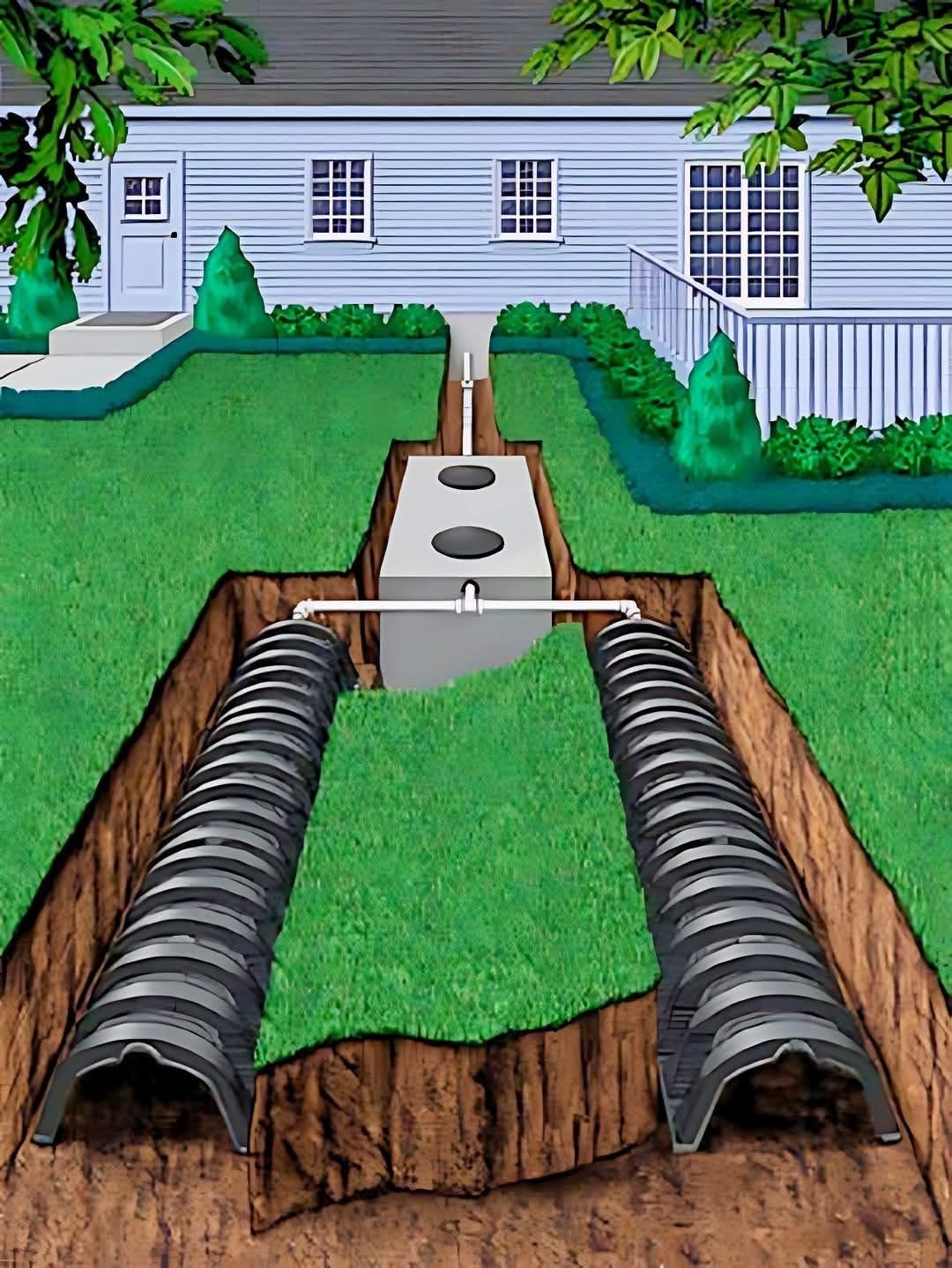
This image is a clear and detailed illustration of a residential septic system, showing its key components buried underground and how they function to treat wastewater from a house.
Here’s a detailed description and understanding of the illustration:
Overall System:
The illustration shows a cross-section of the ground next to a house, revealing the buried components of a septic system. This system is a self-contained wastewater treatment facility used in areas not served by a central municipal sewer system.
Components:
1. Pipe from House: A pipe is shown emerging from the side of the house (where a walkway and steps are visible) and running underground towards the septic tank. This pipe carries all the wastewater from the house’s plumbing fixtures (toilets, sinks, showers, etc.) to the septic system.
2. Septic Tank:
* The illustration shows a large, buried, rectangular tank made of concrete (or similar material).
* It has two circular covers visible at ground level, which are access risers used for inspection and pumping.
* The incoming pipe from the house enters the tank. Inside the tank, baffles (internal walls or tees) are present at the inlet and outlet. These baffles help to slow down the incoming flow, prevent the scum layer from exiting, and keep the settled sludge from disturbing the outgoing effluent.
* The septic tank is where primary wastewater treatment occurs. Solid waste settles to the bottom (forming sludge), and lighter materials like grease and oils float to the top (forming scum). Naturally occurring bacteria in the tank begin to break down some of the organic matter. The liquid layer in the middle is called effluent.
3. Outlet Pipe to Drain Field: A pipe is shown exiting the septic tank’s outlet baffle. This pipe carries the partially treated liquid effluent from the septic tank to the drain field.
4. Distribution Box (Implied/Simplified): Although not explicitly labeled, a small structure or fitting is typically located between the septic tank outlet and the drain field pipes. This is a distribution box (D-box) which evenly distributes the effluent flow to the various pipes in the drain field. In this simplified illustration, the outlet pipe seems to lead directly to the drain field pipes, but in real systems, a D-box is standard for even distribution.
5. Drain Field (Leach Field):
* This is the main part of the secondary treatment system, shown as two parallel trenches dug in the ground.
* Within these trenches are lengths of perforated pipe. The illustration shows black, corrugated pipes with small holes (perforations) along their length.
* These pipes are laid within beds of gravel or crushed stone. The gravel surrounds the pipes and fills the trench below and sometimes above them. This material provides support for the pipes and creates a void space for th
Overall Process:
The illustration effectively summarizes the septic system process: Wastewater flows from the house into the septic tank for initial separation and partial digestion of solids. The liquid effluent then flows to the drain field, where it is distributed through perforated pipes into gravel beds. The effluent then slowly seeps into the surrounding soil, where it is filtered and treated by natural biological processes before returning to the environment. This system is a critical component for wastewater management in areas without access to centralized sewer infrastructure.


